Novel Aircraft Design
Visit the ADRL research page website for the latest information
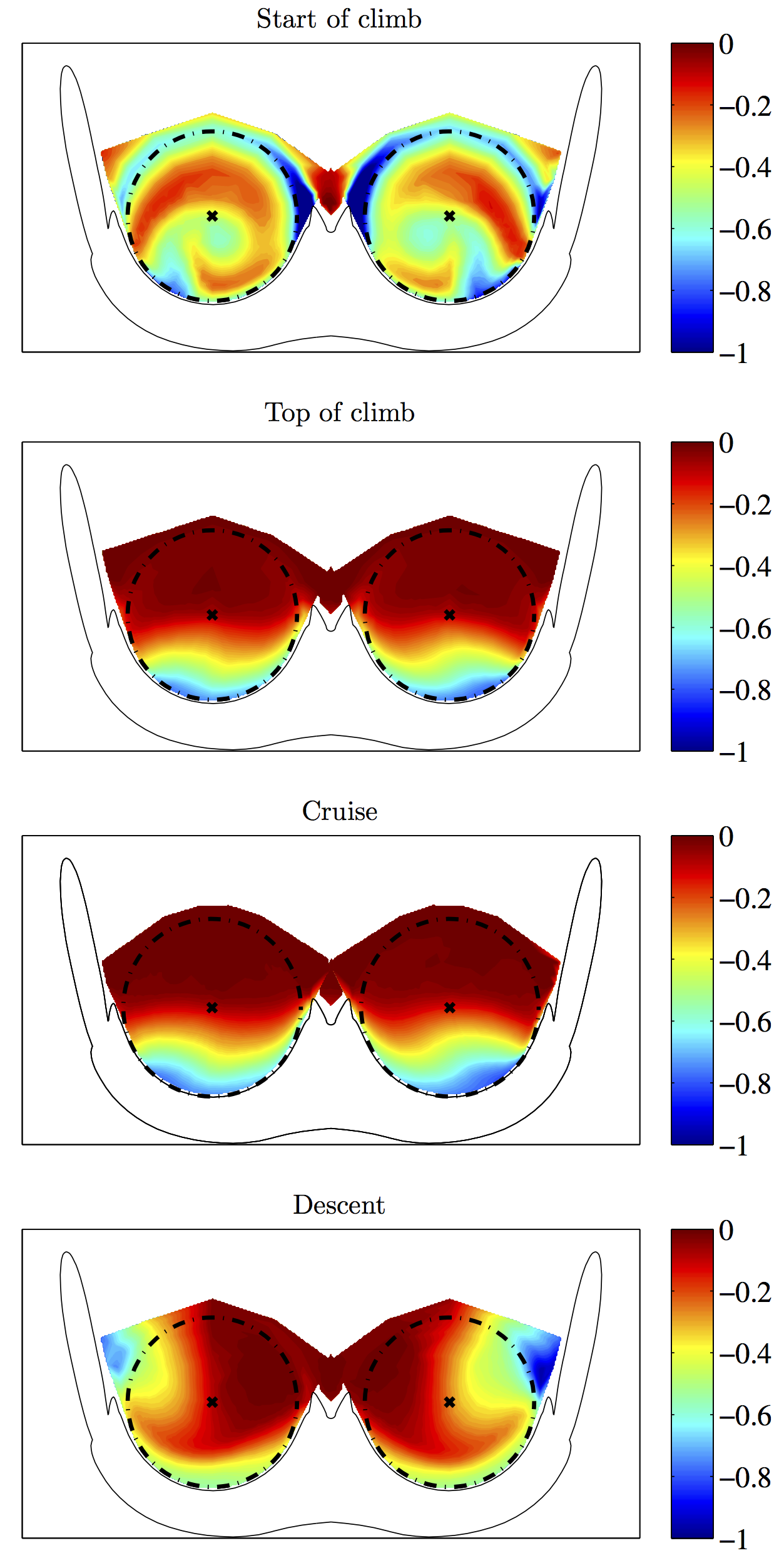
Engine Modeling for CFD
Visit the ADRL research page website for the latest information
Boundary Layer Ingestion (BLI)
Propulsor-Airframe Integration as a Way to Improve Aircraft Performance
Overview
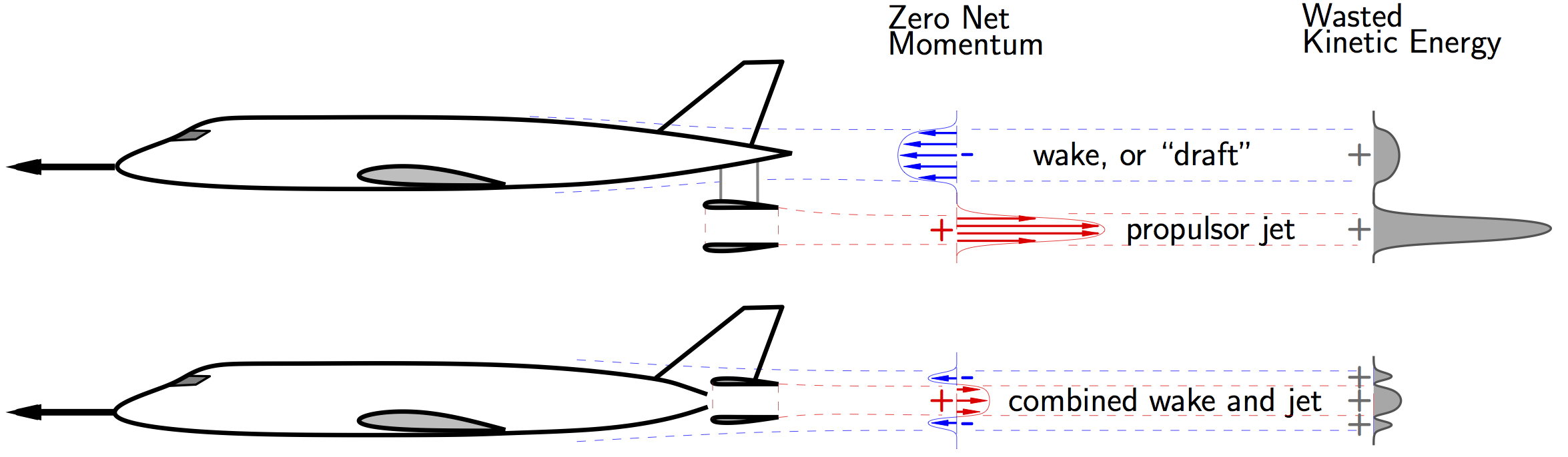
Boundary layer ingestion (BLI) has the potential to provide step improvements in fuel consumption and has been proposed for a number of advanced subsonic transport aircraft concepts With BLI, a portion of the airframe's boundary layer is ingested and re-energized by the propulsors. BLI reduces the overall power dissipation in the flowfield, primarily by reducing wasted kinetic energy in the exhaust jet and also by "filling-in" the wake defect, as illustrated in the figure below.
In order to justify the increased complexity of using BLI, it is important to be able to predict the achievable performance gains, and to understand their physical origins: my research aims at doing this.
One complication of BLI is the force accounting for the entire aircraft, since the usual notions of thrust and drag become ambiguous. A better approach is to consider mechanical energy sources and sinks and analyze BLI using power balance [Drela 2009; Hall et al. 2017; Uranga et al. 2018].
In the power balance framework, the entire aerodynamic flowfield of the airframe plus propulsors is included in one analysis that unifies all the power losses on the aircraft. The surface boundary layer losses of the airframe and the propulsive losses of the power plant are directly related to the power (and hence fuel burn) of the propulsor.
The power balance is formulated on a control volume with inner boundary covering the body surface and spanning the propulsor inlet and exit planes, and an outer boundary effectively at infinity.
In level flight, the difference between the total dissipation in the flowfield and the power added is equal to the streamwise force power (net streamwise force times flight velocity). Thus, only the net streamwise force ("drag minus thrust") is needed and remains well defined.
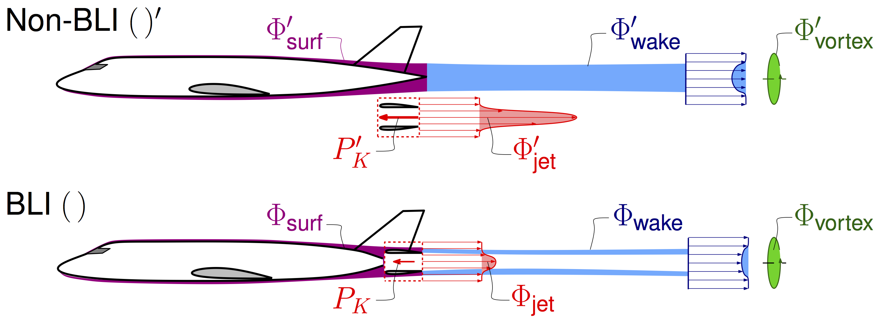
The dissipation can be broken down into surface dissipation occurring in the boundary layers along the aircraft surfaces, wake dissipation in the viscous wakes, vortex dissipation equal to the conventional induced drag power, and jet dissipation in the propulsor jet streams. To counteract these losses, the propulsors add a certain amount of mechanical flow power,
, to the flow. These terms are illustrated in the figure below. Thus, the power balance equation can be written as
where
is the net streamwise force,
the flight velocity,
the rate of climb,
and
the aircraft weight.
The advantageous effects of BLI for transport aircraft can be classified as follows:
- Reduced propulsor jet dissipation for a given force and therefore increased propulsive efficiency: a lower propulsor power is thus required to obtain the same net streamwise force
- Reduced surface dissipation due to the smaller partially- embedded nacelles, that see lower surface velocities
- Reduced wake dissipation due to the propulsors partially elimi- nating the fuselage viscous wake
- Reduced weight due to smaller nacelles and smaller engines (from the reduced power requirement), which in turn enables smaller wings, and thus an even lighter aircraft
The first three effects correspond to comparison of flight power requirements for a given airframe operating at the same lift coefficient, and constitute the aerodynamic benefit of BLI. In a design setting, the airframe can be re-optimized to take full advantage of BLI, thus leading to the fourth benefit source: the system-level benefit. Experimental tests of the D8 configuration demonstrated an aerodynamic benefit from BLI of more than 8% [Uranga et al. 2017], with a total system-level benefit estimated to be close to 19% [Uranga et al. 2014].
References
- A. Uranga, M. Drela, D. Hall, and E. Greitzer, "Analysis of the Aerodynamic Benefit from Boundary Layer Ingestion for Transport Aircraft", AIAA Journal, Vol.56, No. 11, pp. 4271-4281, 2018. doi: 10.2514/1.J056781
- A. Uranga, M. Drela, E.M. Greitzer, D.K. Hall, N.A. Titchener, M.K. Lieu, N.M. Siu, C. Casses, A.C. Huang, G.M. Gatlin, and J.A. Hannon, "Boundary Layer Ingestion Benefit of the D8 Transport Aircraft", AIAA Journal, Vol. 55, No. 11, pp. 3693–3708, 2017. doi: 10.2514/1.J055755
- D.K. Hall, A.C. Huang, A. Uranga, E.M. Greitzer, M. Drela, and S. Sato, "Boundary Layer Ingestion Propulsion Benefit for Transport Aircraft", Journal of Propulsion and Power, Vol. 33, No. 5, pp. 1118–1129, 2017. doi: 10.2514/1.B36321
- M. Drela, "Power Balance in Aerodynamic Flows", AIAA Journal, Vol. 47, No. 7, pp. 1761–1771, 2009.
Close this subsection
MIT/NASA N+3 Program
Aircraft and Technology Concepts for an N+3 Subsonic Transport
Overview
To address the challenges posed by the projected increase in aviation demand and the growing environmental concerns, NASA put forward a multi-phase program starting in 2008 aimed at the development of commercial transport aircraft that could provide step improvements in performance. Named N+3 to refer to the targeted three generations ahead of the current fleet, the program focused on aircraft that could enter into service in the 2025–2035 timeframe.
A team from MIT, Aurora Flight Science, and Pratt & Whitney was initially formed to respond to the solicitation, and was later (in Phase 3) joined by United Technologies Research Center (UTRC), the University of Michigan, and the University of Southern California (USC).
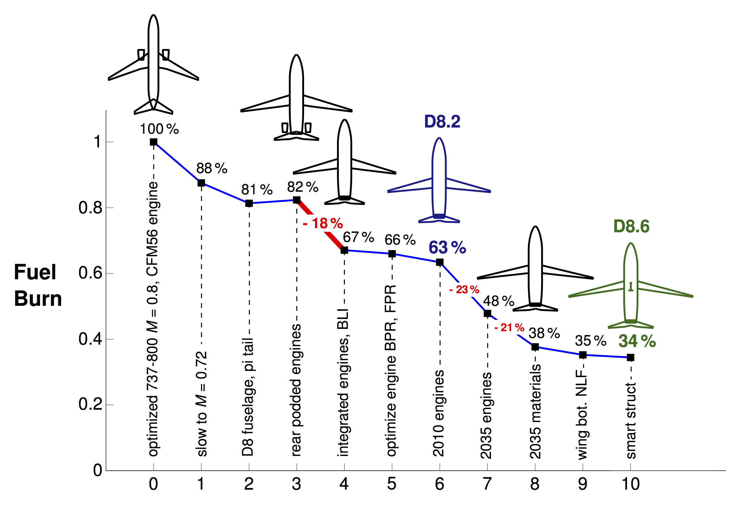
In Phase 1 of the N+3 program (2008-2010), the MIT-led team examined a number of technologies and aircraft concepts, including a 180-passenger D8 "double bubble" aircraft in the Boeing 737-800 or Airbus 320 class, which was predicted to provide a reduction of almost 70% fuel burn compared to the reference 737-800 aircraft. The recognition at the end of Phase 1 was that the D8 held considerable potential, and the two areas with highest uncertainty were identified: the use of boundary layer ingesting (BLI) propulsors and the small core engines needed to drive these.
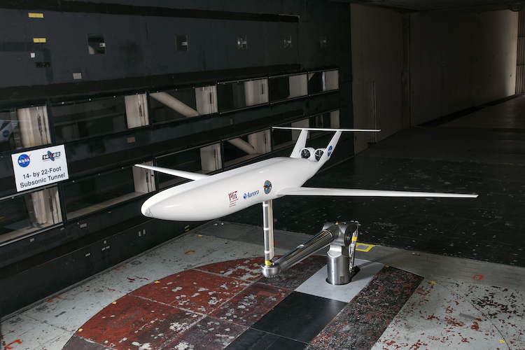
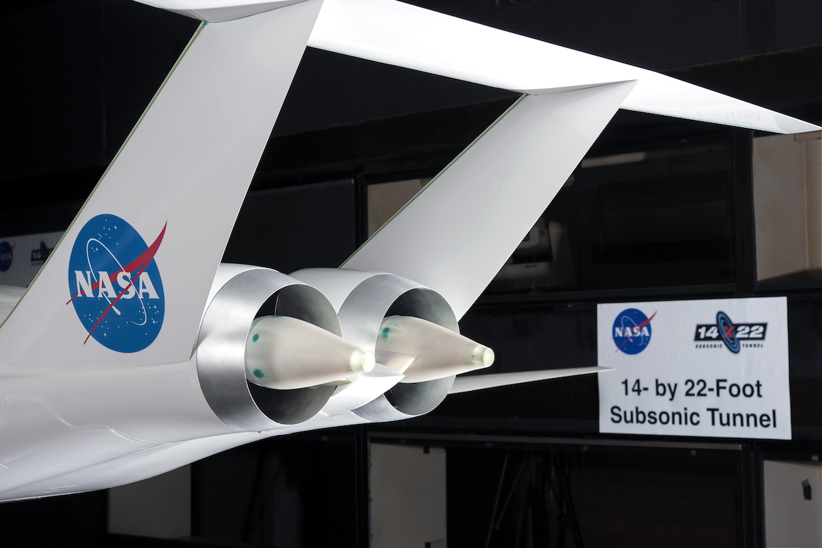
This D8 concept was selected by NASA for further development in a Phase 2 project (2010-2015) with the goal of quantifying the benefit of boundary layer ingestion via a combined experimental and computational effort, and of advancing the readiness level of the highly-efficient, high pressure ratio small core engines that the D8 called for. A major conclusion from the Phase 2 program is that BLI is a viable technology for reducing fuel burn and emissions of commercial subsonic transports. BLI was shown to provide an aerodynamic benefit that amounts to an 8% reduction in power required at cruise, as measured in wind tunnel tests at the NASA Langley 14– by 22–Foot Subsonic Tunnel. Furthermore, an alternative architecture, non-concentric, reversed-core engine was conceptually designed for the D8, which holds considerable promise for future transport aircraft of all types. The Phase 2 work was done in close collaboration with NASA.
Phase 3 (2015-2017) included conceptual-level studies to more precisely determine the fuel-burn benefit of the D-series configuration relative to a conventional tube-and-wing aircraft and its uncertainty. Performance gains related to the use of N+3 technology level assumptions were determined separately from the configuration benefits, as well as the sensitivities to mission range and payload. The design of a transonic D8 aircraft using MDO with coupled aerodynamics-structural-propulsion was also performed, which included definition of the aerodynamic outer-mold-lines and engine characteristics, at a level suitable for experimental and CFD transonic studies.
You will find here a summary of the work. For more information, see the publications listed for each Phase.
Phase 1 (2008-2010)
- E. Greitzer, P. Bonnefoy, E. De la Rosa Blanco, C. Dorbian, M. Drela, D. Hall, R. Hansman, J. Hileman, R. Liebeck, J. Lovergren, P. Mody, J. Pertuze, S. Sato, Z. Spakovszky, C. Tan, J. Hollman, J. Duda, N. Fitzgerald, J. Houghton, J. Kerrebrock, G. Kiwada, D. Kordonowy, J. Parrish, J. Tylko, and D. Wen, "N+3 Aircraft Concept Designs and Trade Studies, Final Report", NASA CR 2010-216794, 2010.
- M. Drela, "Power Balance in Aerodynamic Flows", AIAA Journal, Vol. 47, No. 7, pp. 1761– 1771, 2009.
Phase 2 (2010-2015)
Technology Lead: Alejandra Uranga (formerly MIT)
Chief Engineer: Mark Drela (MIT)
Participating organizations: MIT, Aurora Flight Sciences, Pratt & Whitney,
Abstract
The aerodynamic benefit of BLI at cruise was quantified to be 8.6% at fixed nozzle area, through a back-to-back comparison of non-BLI and BLI versions of the D8, which included low-speed tests of 1:11 scale powered models in the NASA Langley 14– by 22–Foot Subsonic Tunnel. This represents the first measurement of BLI performance improvements for a realistic aircraft configuration. A novel engine architecture with a nonconcentric, reverse-flow arrangement of the core and fan sections was conceived to satisfy the FAA 1-in-20 engine failure rule for the D8 aircraft's integrated propulsion system with side-by-side engines. The BLI benefit results, coupled with the innovative engine design, give evidence that aircraft using BLI can provide a viable path for step improvements in fuel efficiency of subsonic transports.
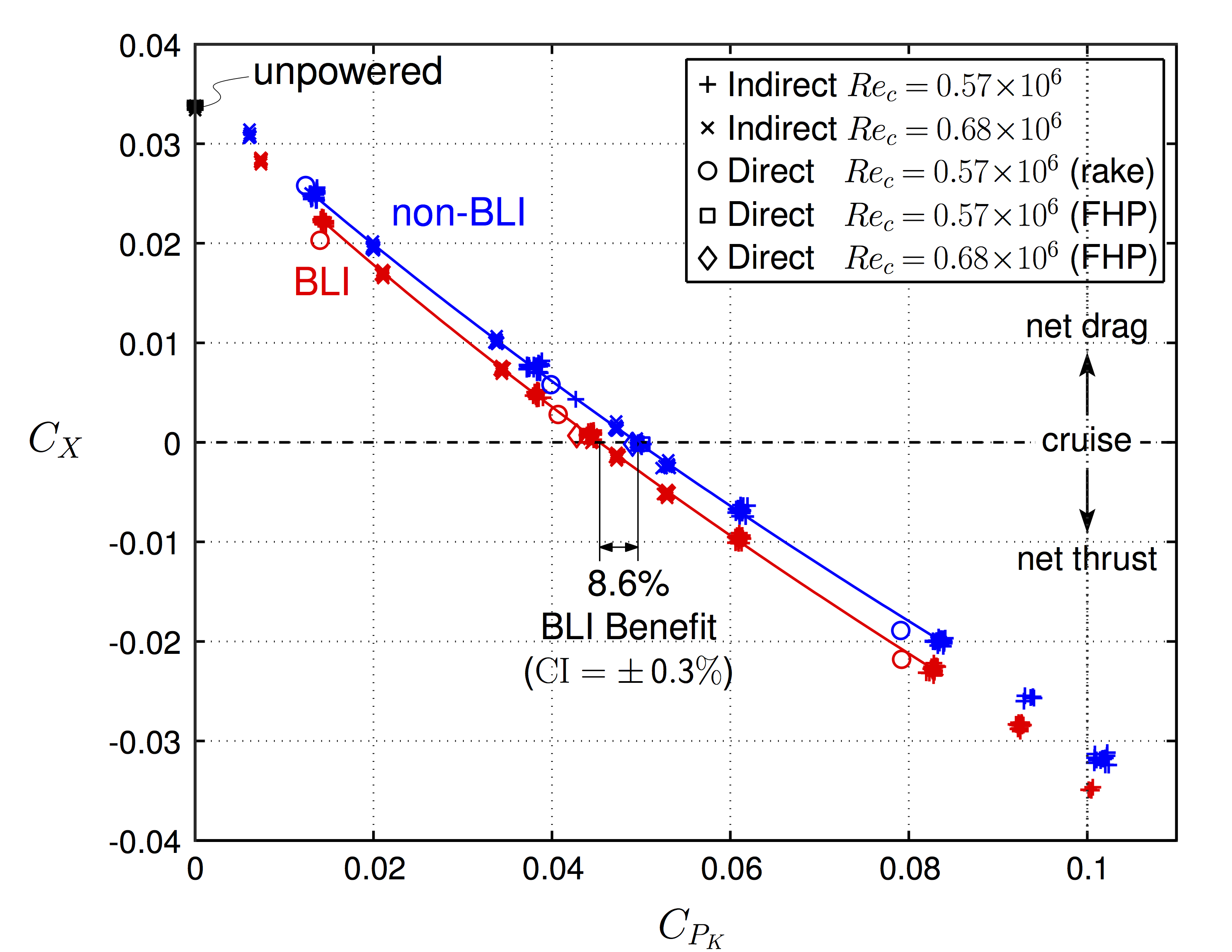
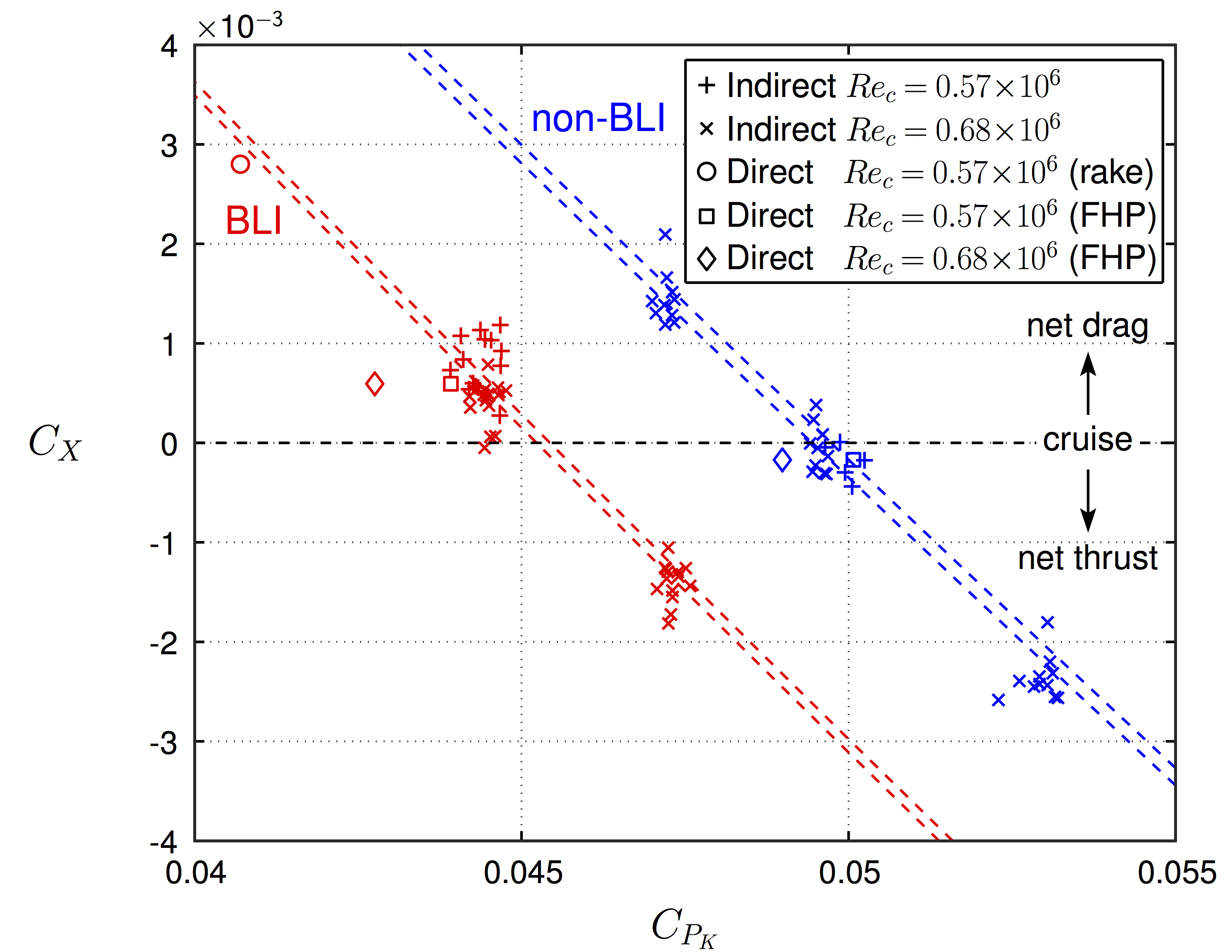
BLI deduces the required power by about 8% at cruise (zero net force condition) when the same propulsor is used on both configurations.
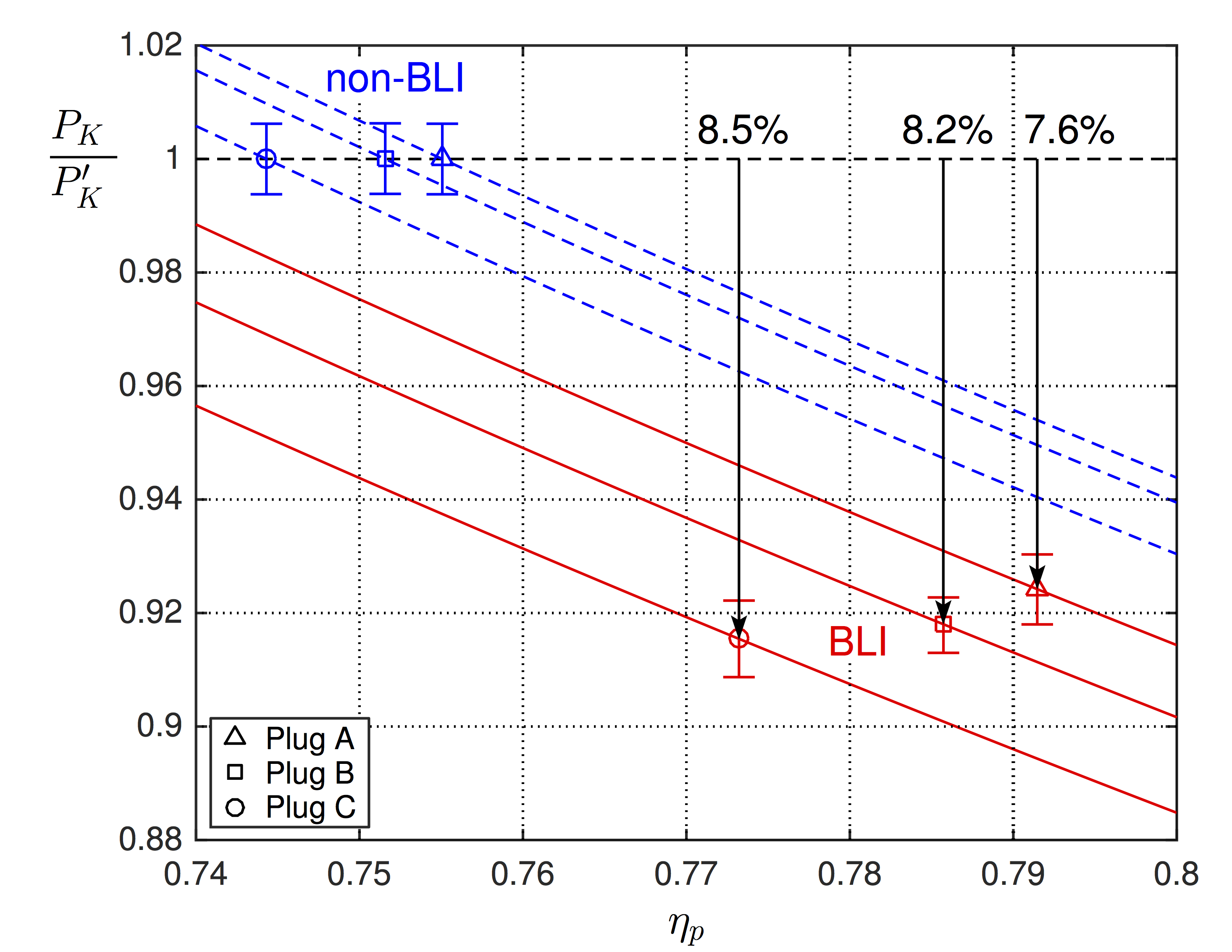
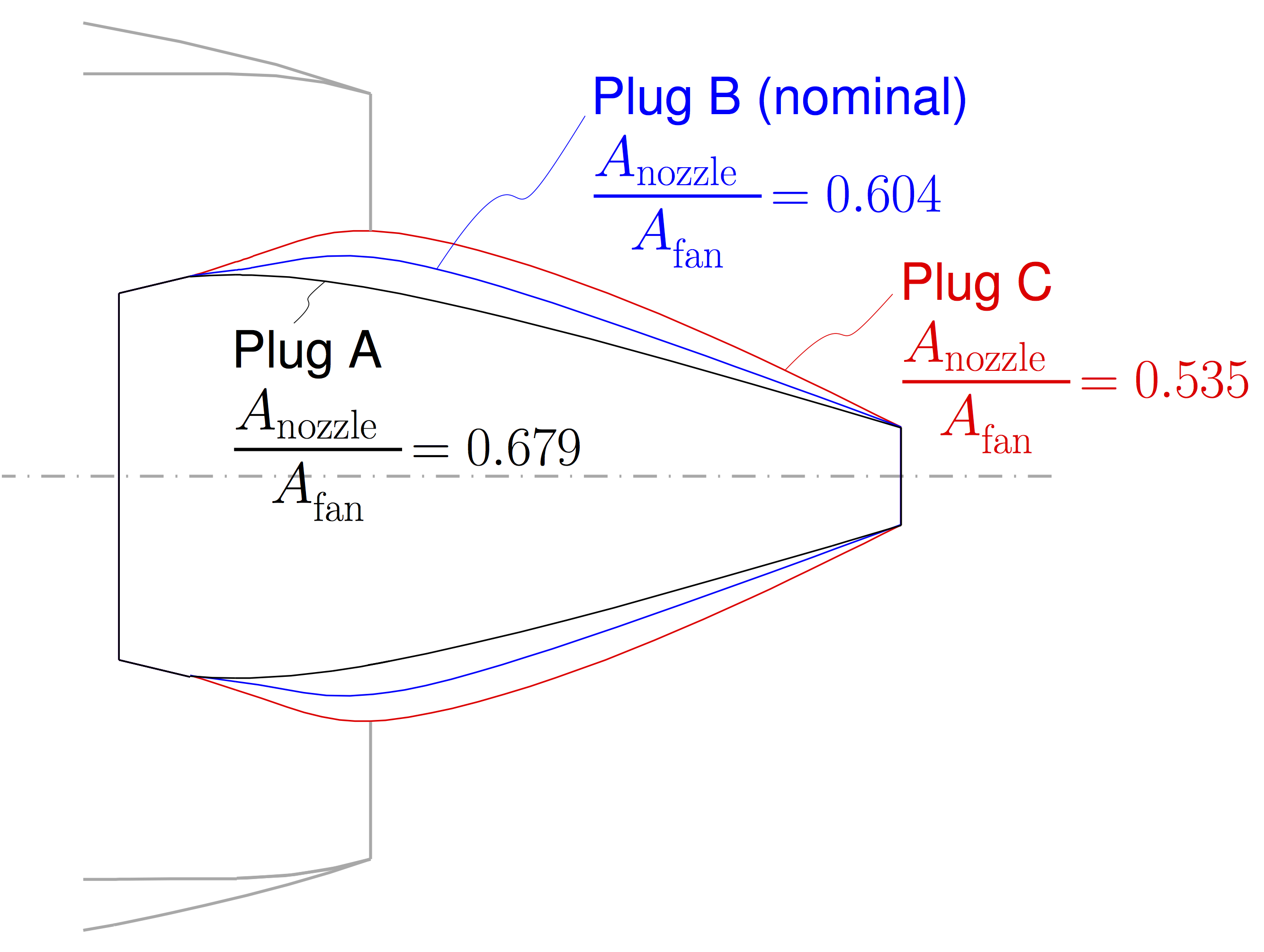
Different plugs (nozzle areas) result in different propulsive efficiencies and slightly different surface dissipations, thus produce a range of aerodynamic BLI benefits.
References
- A. Uranga, M. Drela, E. Greitzer, C. Casses, A. DiOrio, A. Espitia, A. Grasch, D. Hall, A. Huang, M. Lieu, S. Sato, N. Siu, C. Tan, N. Titchener, E. van Dam, J. Hollman, D. Kordonowy, R. Opperman, J. Chambers, B. Smith, E. Pliakas, A. Cardona, S. Giblin, D. Campbell, W. Lord, and G. Suciu, "Aircraft and Technology Concepts for an N+3 Subsonic Transport, Phase 2 Final Report", GTL Report Series 2, Report No. 2-001, Gas Turbine Laboratory, Massachusetts Institute of Technology, 2018.
- A. Uranga, M. Drela, E. Greitzer, D. Hall, N. Titchener, M. Lieu, N. Siu, C. Casses, A. Huang, G. Gatlin, J. Hannon, "Boundary Layer Ingestion Benefit of the D8 Transport Aircraft", AIAA Journal, Vol. 55, No. 11, pp. 3693–3708, 2017. doi: 10.2514/1.J055755
- A. Uranga, M. Drela, D. Hall, and E. Greitzer, "Analysis of the Aerodynamic Benefit from Boundary Layer Ingestion for Transport Aircraft", AIAA Journal, in press, 2018.
- D. Hall, A. Huang, A. Uranga, E. Greitzer, M. Drela, and S. Sato, "Boundary Layer Ingestion Propulsion Benefit for Transport Aircraft", Journal of Propulsion and Power, Vol. 33, No. 5, pp. 1118–1129, 2017. doi: 10.2514/1.B36321
- M. Drela, "Development of the D8 transport configuration", AIAA 2011-3970, 29th AIAA Applied Aerodynamics Conference, Honolulu, HI, , 27-30 June 2011.
- M. Lieu, A. Uranga, M. Drela, and E. Greitzer, "Rapid Flow Surveys via Rotating Rake System and Use in Powered Wind Tunnel Models" , AIAA 2014-2801, 30th AIAA Aerodynamic Measurement Technology and Ground Testing Conference, Atlanta, Georgia, 16-20 June 2014. doi: 10.2514/6.2014-2801
- N. Siu, N. Titchener, C. Casses, A. Huang, A. Uranga, M. Drela, and E. Greitzer, "Evaluating Propulsor Mechanical Flow Power in Powered Aircraft Wind Tunnel Experiments" , AIAA-2014-2566, 32nd AIAA Applied Aerodynamics Conference, Atlanta, Georgia, 16-20 June 2014. doi: 10.2514/6.2014-2566
- A. Uranga, M. Drela, E. Greitzer, N. Titchener, M. Lieu, N. Siu, A. Huang, G. Gatlin, and J. Hannon, "Preliminary Experimental Assessment of the Boundary Layer Ingestion Benefit for the D8 Aircraft" , AIAA-2014-0906, 52nd AIAA Aerospace Sciences Meeting, SciTech 2014, National Harbor, Maryland, 13-17 Jan. 2014. doi: 10.2514/6.2014-0906
- S. Pandya, A. Huang, A. Espitia, and A. Uranga, A., "Computational Assessment of the Boundary Layer Ingesting Nacelle Design of the D8 Aircraft" AIAA-2014-0907, 52nd AIAA Aerospace Sciences Meeting, Science and Technology Forum and Exposition, SciTech2014, National Harbor, Maryland, 13-17 Jan. 2014. doi: 10.2514/6.2014-0907
Phase 3 (2015-2017)
co-PI: Ed Greitzer (MIT)
Participating organizations: Massachusetts Institute of Technology, University of Southern California, United Technologies Research Center, Pratt & Whitney, University of Michigan
Abstract
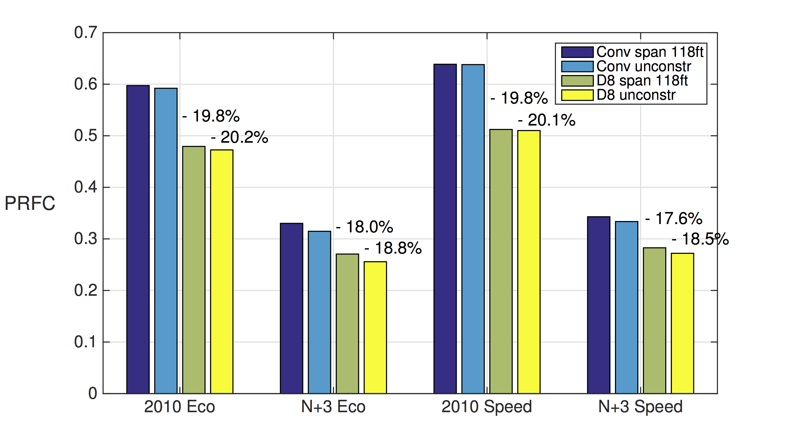
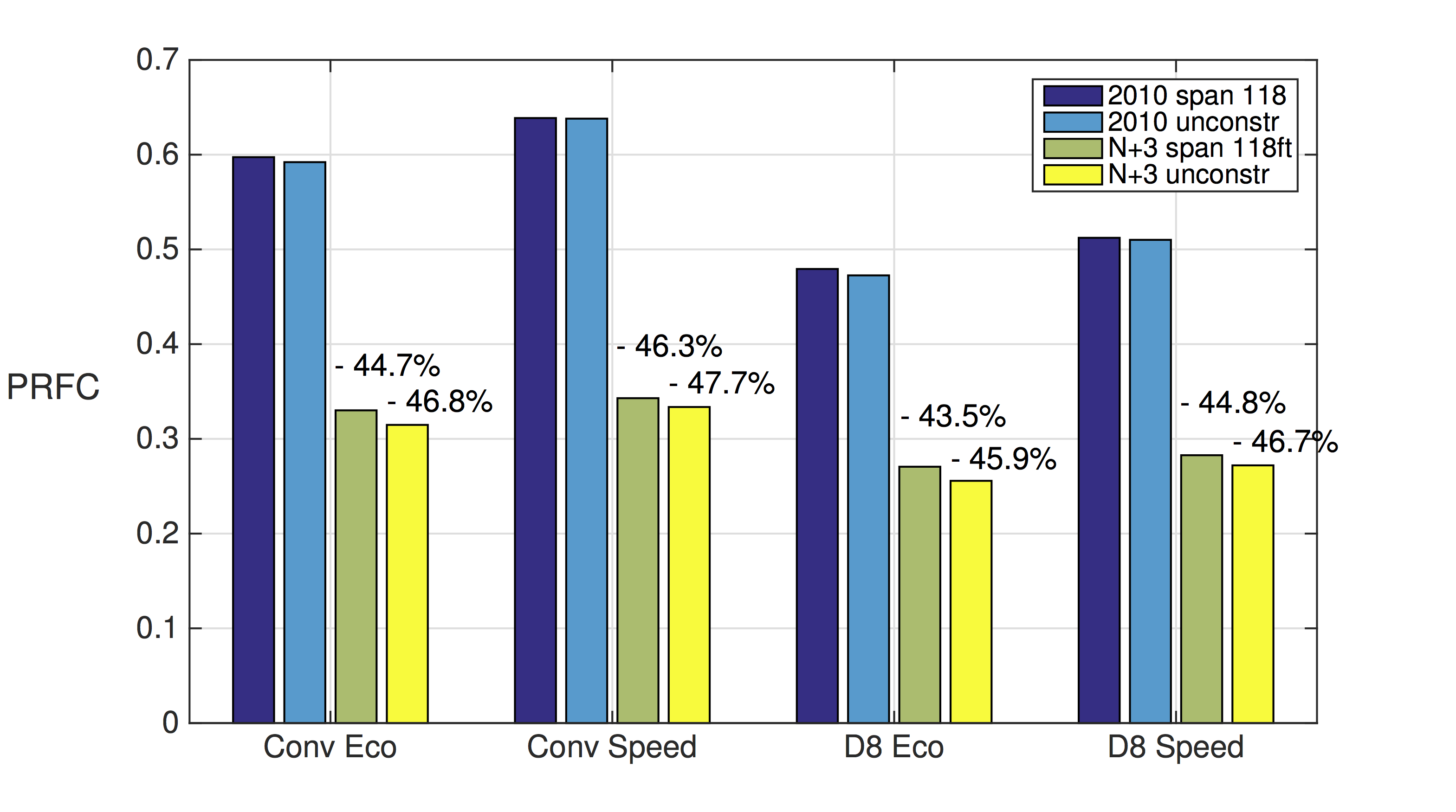
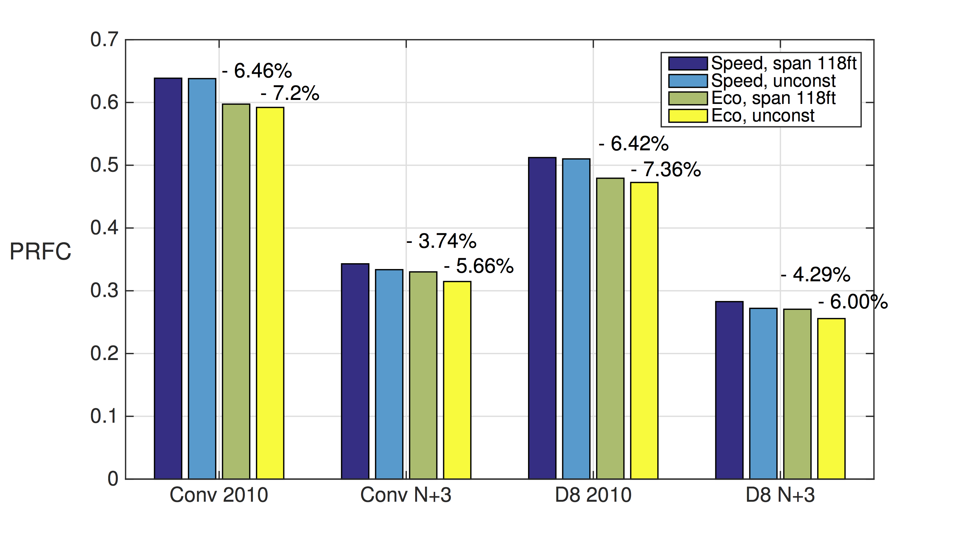
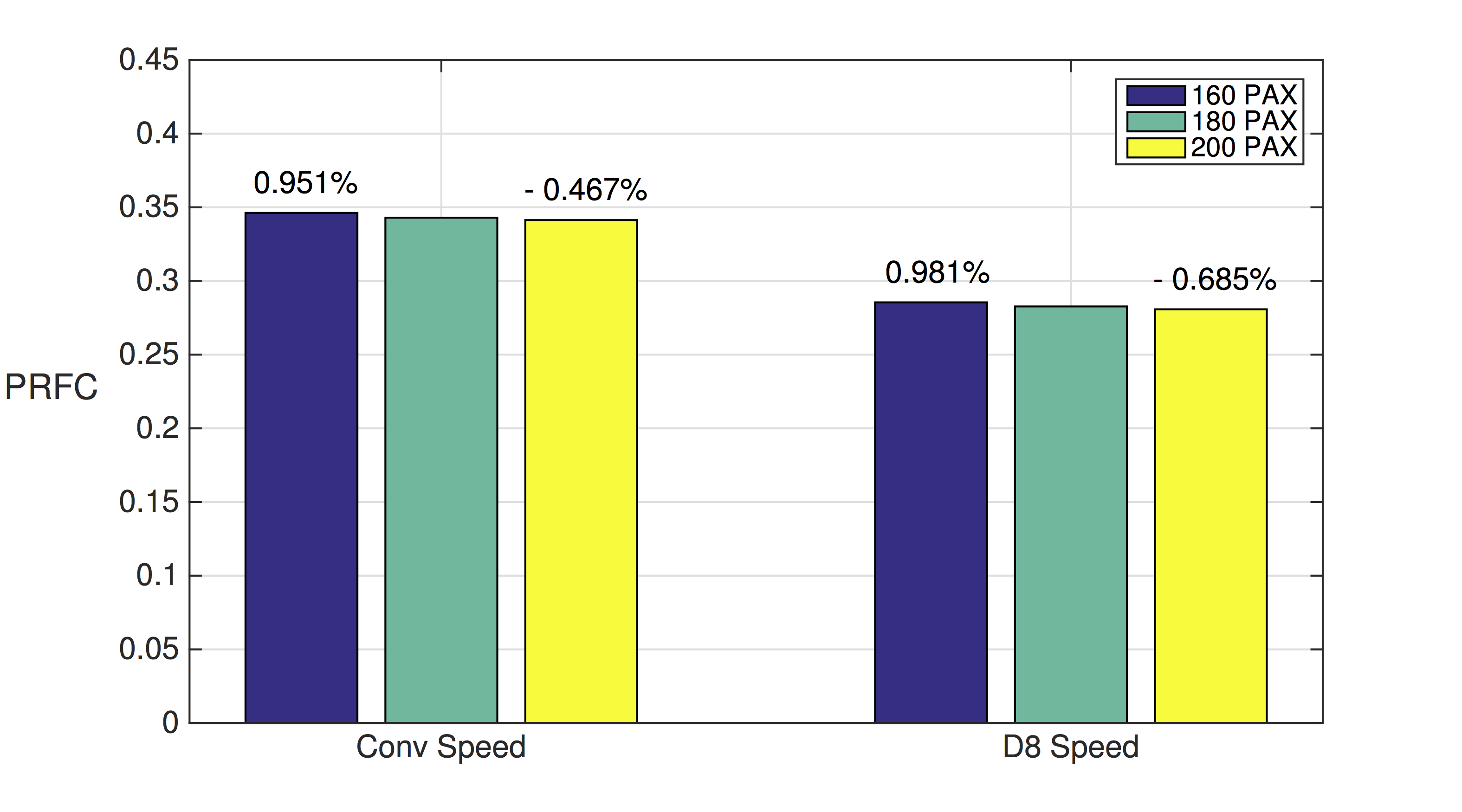
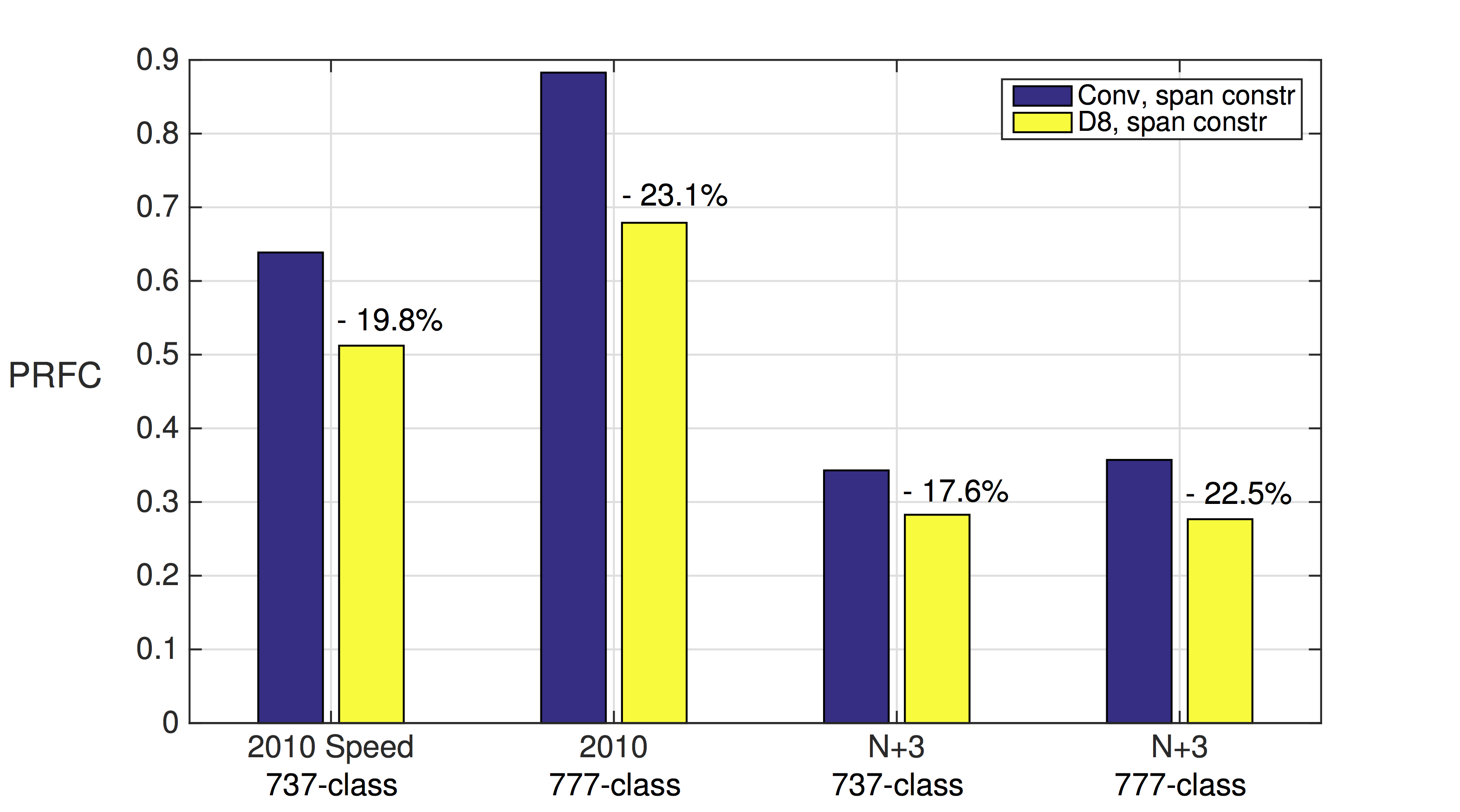
Through conceptual-level studies, we determined the fuel-burn benefit of the D-series configuration relative to a conventional tube-and-wing aircraft and its uncertainty. This benefit amounts to between 17.6% and 23.1% lower fuel burn depending of how the comparison is made. It is present in spite of, and is much larger than, pessimistic fan performance penalties resulting from boundary layer ingestion (BLI) as determined by analysis of fan efficiency losses and weight gains.
Multi-disciplinary design optimization (MDO) was used to design a transonic D8 via aero-structural optimization with a weakly coupled propulsion system. The outcome is a plausible design, at a level of detail suitable for CFD study or wind tunnel experiments, and comprised of outer-mold lines (including propulsor integration), major structural elements, and design-point engine characteristics for cruise speeds of Mach 0.72 and Mach 0.78. This preliminary high-fidelity optimization of the aft fuselage geometry highlight the complexities of integrated propulsion modeling, design, and optimization.
Definitions
- Performance Metric: Payload-Range Fuel Consumption, PRFC: defined as the fuel energy consumed divided by the product of payload weight and range; non-dimensionless number quantifying fuel energy consumed relative to the mission productivity (payload times range)
-
Aircraft
- Conventional configuration: tube-and-wing aircraft with a with circular fuselage cross-section, conventional empennage, and two engines mounted under the wings
-
D-series configuration: aircraft with a double-bubble lifting fuselage, and two BLI engines mounted on the top aft fuselage under a pi-tail
- D8: Mid-range D-series aircraft transporting 180 passenger over a range of 3,000 nm
- D12: Long-range D-series aircraft transporting 450 passengers over range of 7,500 nm
All aircraft considered are single-class with only economy seats. The payload weight is set by multiplying the number of passengers by a per passenger+baggage weight of 215 lb.
-
Missions
-
Mid-range: 737-class mission of 180 passengers (38,700 lb payload) transported over 3,000 nm range
- Eco or e: Mid-range aircraft cruising at Mach 0.72
- Speed or s: Mid-range aircraft cruising at Mach 0.78
- Long-range: 777-class mission of 450 passengers (96,750 lb payload) transported over 7,500 nm range with cruise Mach number of 0.84
-
Mid-range: 737-class mission of 180 passengers (38,700 lb payload) transported over 3,000 nm range
-
Technologies
- Baseline technology: technology level used on the majority of aircraft flying in 2010. It is characterized by the use of primarily aluminum materials, and engines of the type of a CFM-56 (when considering mid-range mission) or GE90 (when considering long range missions)
- N+3: technology or aircraft that is ready for entry into service in 2035. It is characterized by the use of primarily composite materials and advanced engines. The specific characteristics of such an engine will be defined in the body of this report
-
Mission Technology Cruise Speed Range Payload Mid-Range Eco 8.2e Baseline Mach 0.72 3,000 nmi 180 PAX (38,700 lb) 8.6s N+3 Mid-Range Speed 8.2s Baseline Mach 0.78 3,000 nmi 180 PAX (38,700 lb) 8.6s N+3 Long Range 12.2 Baseline Mach 0.84 7,500 nmi 450 PAX (96,750 lb) 12.6 N+3
Conceptual Study Results

References
- A. Uranga, E.M. Greitzer, M. Drela, D.K. Hall, Y. Chen, S. Ochs, G. Tillman, D. Voytovych, W. Lord, J.R.R.A. Martins, C.A. Mader, and G.K.W. Kenway, "Transonic D8 Performance and Design - Aircraft and Technology Concepts for an N+3 Subsonic Transport, Phase 3 Final Report", NASA CR, to appear, 2018.
- C.A. Mader, G.K. Kenway, J. Martins, and A. Uranga, "Aerostructural Optimization of the D8 Wing with Varying Cruise Mach Numbers", AIAA 2017-4436, AIAA Aviation 2017, 18th AIAA/ISSMO Multidisciplinary Analysis and Optimization Conference, 2017.
Close this subsection
D8 Double-Bubble Aircraft
Aircraft Concept Overview
Overview
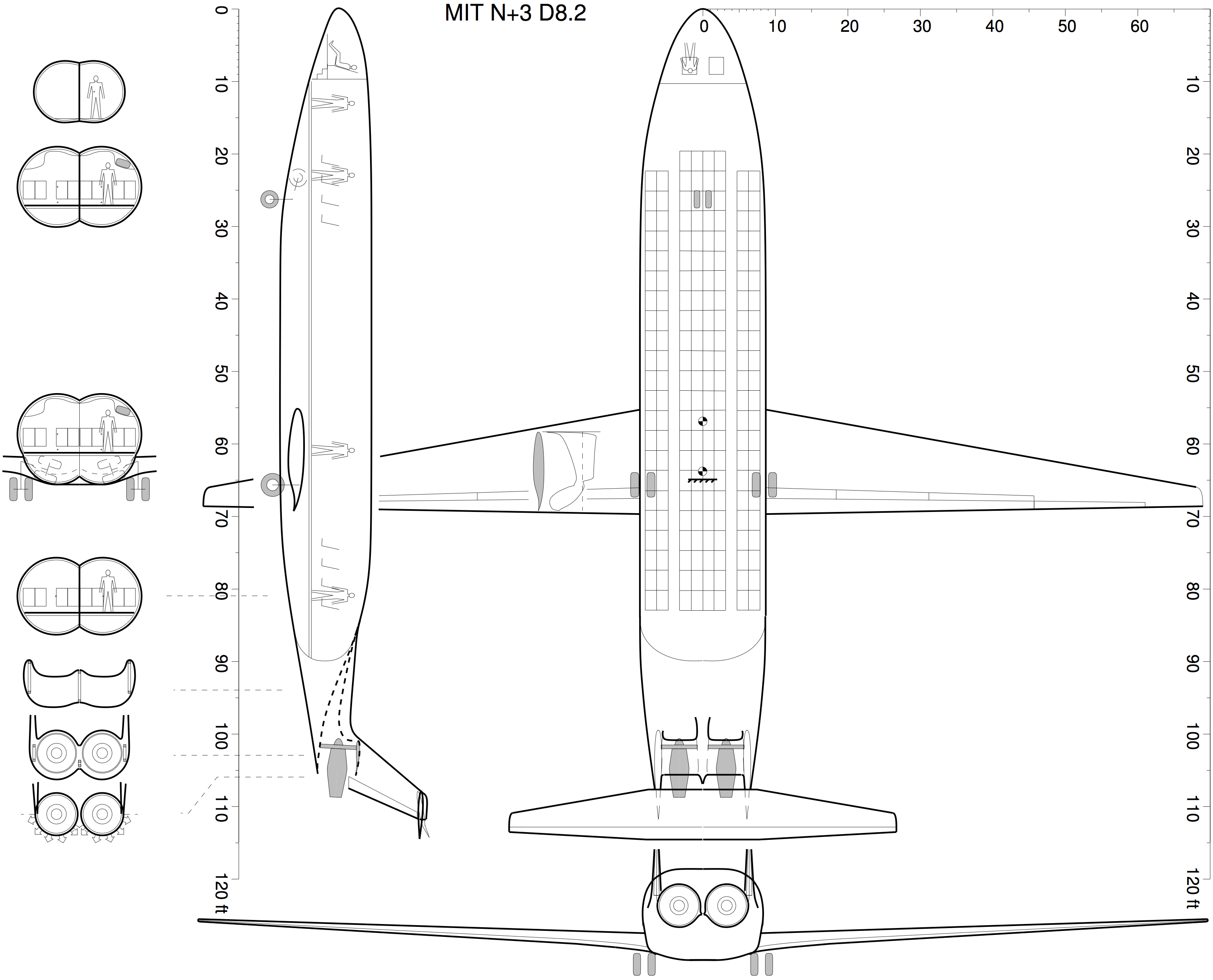
The D8 "double-bubble" aircraft, named for its characteristic fuselage cross-section,
is a 180-passenger, 3 000 nm range transport in the Boeing 737 or Airbus A320 aircraft class.
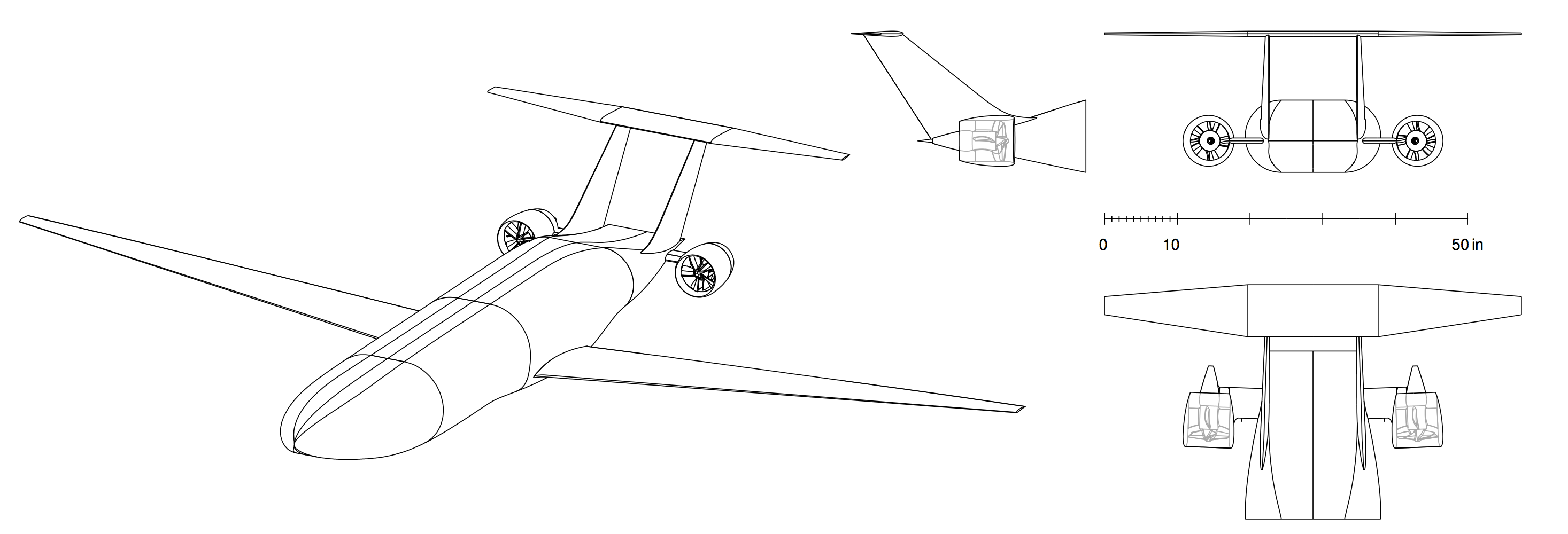
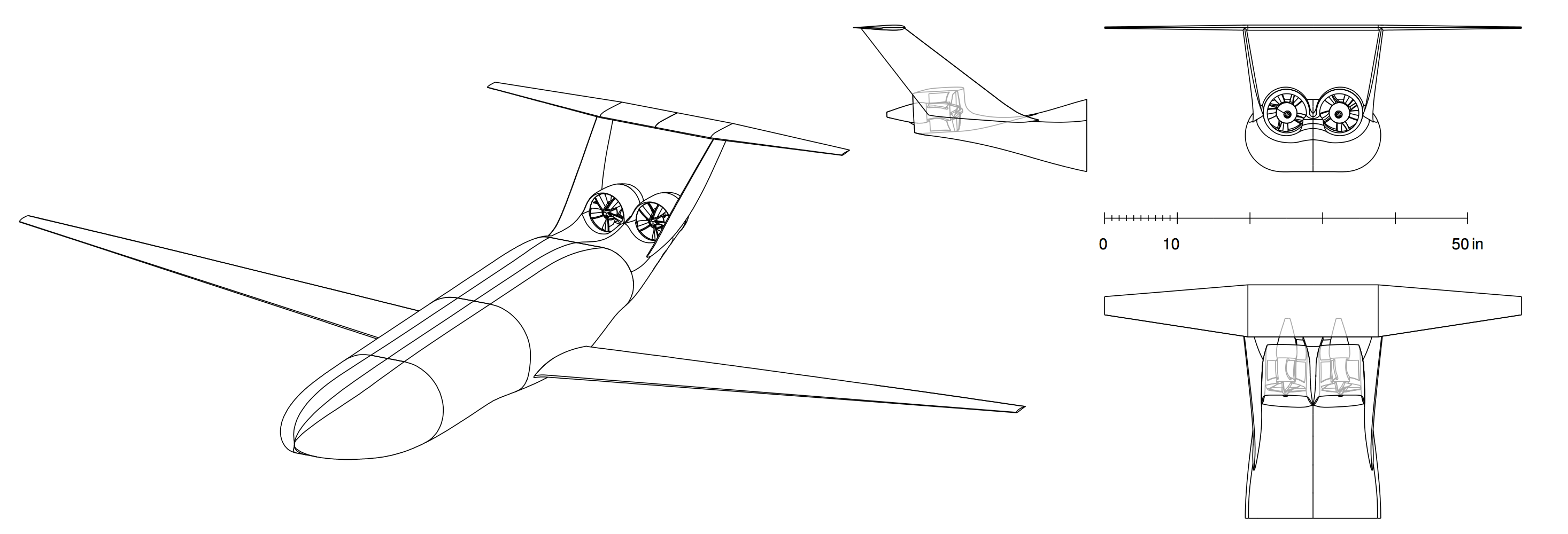
This MIT-designed aircraft concept is characterized by a wide twin-aisle lifting fuselage which enables the use of smaller, lighter wings and a pi-tail empennage with the horizontal tail supported by twin vertical tails. The fuselage nose shape provides a nose-up pitching moment that reduces the trimming tail down-force in cruise and further shrinks both the wing and horizontal tail areas. A low-sweep wing that contributes to a lighter structure is made possible by a cruise speed of Mach 0.72, compared to around Mach 0.78 for a conventional tube-and-wing aircraft in the same class.
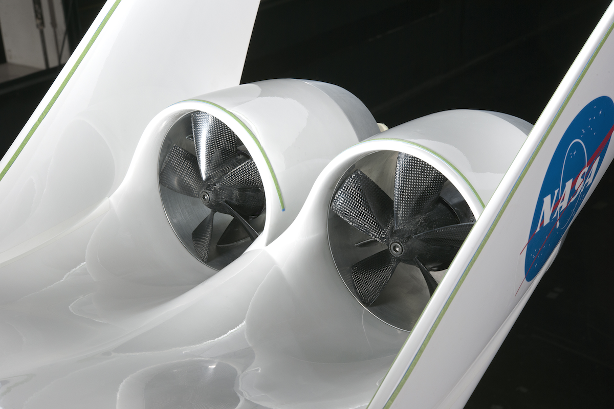
A major feature of the D8 configuration is the use of boundary layer ingestion (BLI): the engines are flush-mounted on the top rear of the fuselage, and ingest approximately 13% of the total airframe viscous dissipation (or roughly 40% of the fuselage boundary layer), with the BLI ingestion fractions given as based on boundary layer kinetic energy defect. The fuselage performs much of the diffusion and flow alignment into the fans, which would otherwise be achieved by the nacelle. The D8 nacelles are thus smaller than for conventional podded engines, saving weight and reducing external losses.
The D8 was first designed by M. Drela during MIT's NASA-funded Phase 1 N+3 project, and later refined during Phases 2 (low-speed geometry and engine integration lines) and Phase 3 (high-speed outer-mold-line). The first D8 studies during the N+3 Phase 1 project employed three engines. Switching to two engines results in a slight performance decrease but addresses cost and maintenance concerns, and so a twin-engine installation was chosen early during the N+3 Phase 2 project.
After completion of the 3 phases in the NASA-funded N+3 project at MIT, the D8 was further developed by Aurora Flight Sciences, now a Boeing Company.
References
- Drela, M.: "Power Balance in Aerodynamic Flows". AIAA Journal, Vol. 47, No. 7, pp. 1761– 1771, 2009.
- Greitzer, E. M.; Bonnefoy, P.; De la Rosa Blanco, E.; Dorbian, C.; Drela, M.; Hall, D.; Hans- man, R.; Hileman, J.; Liebeck, R.; Lovergren, J.; Mody, P.; Pertuze, J.; Sato, S.; Spakovszky, Z.; Tan, C.; Hollman, J.; Duda, J.; Fitzgerald, N.; Houghton, J.; Kerrebrock, J.; Kiwada, G.; Kordonowy, D.; Parrish, J.; Tylko, J.; and Wen, E.: "N+3 Aircraft Concept Designs and Trade Studies, Final Report", NASA CR 2010-216794, 2010.
- Uranga, A.; Drela, M.; Greitzer, E.; Casses, C.; DiOrio, A.; Espitia, A.; Grasch, A.; Hall, D.; Huang, A.; Lieu, M. K.; Sato, S.; Siu, N.; Tan, C.; Titchener, N.; van Dam, E.; Hollman, J.; Kordonowy, D.; Opperman, R.; Chambers, J.; Smith, B.; Pliakas, E.; Cardona, A.; Giblin, S.; Campbell, D.; Lord, W.; and Suciu, G.: "Aircraft and Technology Concepts for an N+3 Subsonic Transport, Phase 2 Final Report". GTL Report Series 2, Report No. 2-001, Gas Turbine Laboratory, Massachusetts Institute of Technology, 2018.
- Uranga, A., Drela, M., Greitzer, E., Titchener, N., Lieu, M., Siu, N., Huang, A., Gatlin, G., and Hannon, J., "Preliminary Experimental Assessment of the Boundary Layer Ingestion Benefit for the D8 Aircraft" , AIAA-2014-0906, 52nd AIAA Aerospace Sciences Meeting, SciTech 2014, National Harbor, Maryland, 13-17 Jan. 2014. doi: 10.2514/6.2014-0906
- A. Uranga, M. Drela, E. Greitzer, D. Hall, N. Titchener, M. Lieu, N. Siu, C. Casses, A. Huang, G. Gatlin, J. Hannon, "Boundary Layer Ingestion Benefit of the D8 Transport Aircraft", AIAA Journal, Vol. 55, No. 11, pp. 3693–3708, 2017. doi: 10.2514/1.J055755
Close this subsection
Transition at Low Reynolds Numbers (PhD Thesis Work)
Investigation of transition to turbulence at low Reynolds numbers using Implicit Large Eddy Simulations with a Discontinuous Galerkin method
Overview
My PhD research involved the use of high-order Discontinuous Galerkin methods for the simulation of transition to turbulence in flows at low and moderate Reynolds numbers. My thesis work was supervised by Jaime Peraire and Mark Drela of MIT, and I worked closely with Per-Olof Persson of UC Berkeley.
You will find here a summary of the work. For more information, see the following Publications:
-
A. Uranga,
"Investigation of Transition to Turbulence at Low Reynolds Numbers Using Implicit Large Eddy Simulations with a Discontinuous Galerkin Method"
,
PhD thesis, Dept. of Aeronautics and Astronautics, Massachusetts Institute of Technology, Cambridge, MA, USA, Sept. 2010 (degree date: Feb. 2011).
- A. Uranga, P.-O. Persson, M. Drela, and J. Peraire, "Preliminary Investigation Into the Effects of Cross-Flow on Low Reynolds Number Transition", 20th AIAA Computational Fluid Dynamics Conference, AIAA-2011-3558, Honolulu, Hawaii, June 27-30, 2011.
- A. Uranga, P.-O. Persson, M. Drela, and J. Peraire, "Implicit Large Eddy Simulation of transition to turbulence at low Reynolds numbers using a Discontinuous Galerkin method", International Journal for Numerical Methods in Engineering, Vol. 86, 2011.
- A. Uranga, P.-O. Persson, M. Drela, and J. Peraire, "Implicit Large Eddy Simulation of transitional flows over airfoils and wings", 19th AIAA Computational Fluid Dynamics Conference, AIAA-2009-4131, San Antonio, Texas, June 22-25, 2009.
Abstract
This work predicts the formation of laminar separation bubbles at low Reynolds numbers and the related transition to turbulence. In addition to being one of the first Implicit Large Eddy Simulation studies using a high-order Discontinuous Galerkin method, unique attention is given to the boundary layer characteristics thus contribut- ing to the understanding of low Reynolds number flows and the related separation- induced transition. Furthermore, a preliminary transition model suitable for such flows is introduced and its underlying concept proven valid.
The flow around an SD7003 infinite wing at an angle of attack of 4 degrees is first con- sidered at Reynolds numbers of 10,000, 22,000, and 60,000. At the lowest Reynolds number studied, the flow remains laminar and two dimensional with a periodic vor- tex shedding. For higher Reynolds numbers, the flow is highly unsteady and exhibits a separation bubble on the upper surface over which flow transitions to turbulence. Tollmien-Schlichting waves are observed in the boundary layer upstream of separation, and their streamwise amplification factor shows they are responsible for transition.
The major effects of cross-flow on low Reynolds number transition are studied by comparing the flows over the same infinite wing at different sweep angles. Projecting the results along a common two-dimensional equivalent direction, it is established that the cross-flow cannot be decoupled from the streamwise evolution at intermediate sweep angles due to strong non-linear interactions that take place after the laminar boundary layer separates. Hence, for separation-induced transition at low Reynolds numbers, it is not possible to treat streamwise and cross-flow instabilities indepen- dently for wings with sweep angles between about 10◦ and 40◦, and predicting the mixed transition cannot be reduced to treating the disturbances of each component separately. An important presumption to be adopted in the study of unsteady flows for MAVs and animal locomotion is thus that the type of transition (TS dominated, cross-flow dominated, or mixed) is a priori unknown as soon as the flow is slightly misaligned with the wing's chord.
Numerical Method
The compressible, unsteady, Navier-Stokes equations are solved using a high-order Discontinuous Galerkin (DG) method. The inviscid terms of the numerical fluxes are evaluated with a Roe solver [9], while viscous terms are treated using the Compact Discontinuous Galerkin (CDG) method [7]. The later is a compact method that results in a sparser connectivity matrix than the alternative methods such as the BR2 method [2] and the Local Discontinuous Galerkin (LDG) method [3].
Time integration is performed using the third-order accurate diagonal implicit Runge-Kutta (DIRK) scheme [1]. The non-linear system of equations is solved using Newton's method with a block-ILU/multigrid preconditioned Conjugate Gradient Squared (CGS) solver for the each linear iteration [8].
Following the implicit Large Eddy Simulation (ILES) approach, the fully (unfiltered) compressible Navier-Stokes equations are solved; the unresolved small eddies are accounted for by means of the numerical dissipation, and no sub-grid-scale model is employed.
Problem Setup
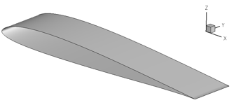
The flow aroung a rectangular wing with an SD7003 airfoil profile is considered, at an angle of attack of 4 degrees, and at Reynolds numbers of 10,000 and 60,000.
The freestream Mach number is set to 0.2, which is low enough that the flow is fundamentally incompressible but high enough to improve numerical stability. The fluid is air with a Prandtl number of 0.72 and specific heat ratio of 1.4, and the kinematic viscosity is assumed constant.
|
The axes are setup as shown in the figure, with x being the chord-wise direction (with the leading-edge at x=0), y the span-wise direction, and z is vertically up. The wing span-to-chord ratio is set to 0.2, following the findings of Galbraith and Visbal [5].
Extensive experimental data is available for comparison [6], as well as numerical simulations [5]. |
 |
Computational Grid
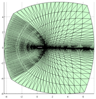
The computational domain has periodic boundary conditions along the span-wise direction, in order to simulate an infinite wing. The wing's surface is represented by a non-slip, adiabatic, boundary condition, while a full-state type boundary condition is imposed at the far-field of the computational domain.
|
The computational domain extends 4.3 chord lengths upstream of the wing's leading edge, 5.9 chord lengths above the wing's leading edge line, 6.0 chord lengths below the wing's leading edge line, and 6.43 chord lengths downstream of the wing's trailing edge. Thus, if we denote by c the chord length, the domain spans on the range [-4.3c , 7.4c] x [0 , 0.2c] x [-6.0c , 5.9c] along the chord-wise, span-wise, and vertical directions, respectively.
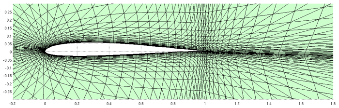
The results that follow where obtained on a computational grid with 52,800 tetrahedral elements and 1,056,000 degrees-of-freedom. Third-order polynomials are used, thus resulting in a fourth-order accurate method in space. The following images show the computational grid on a planar cut along the span-wise direction. |
 |
|
Results
At a Reynolds number of 10,000 the flow is found to be fundamentally two-dimensional with little variation along the spanwise direction and close-to-periodic vortex shedding.
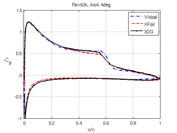
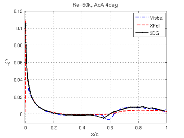
On the contrary, at a Reynolds number of 60,000, three-dimensional structures are present as made visible by contours of vorticity or q-criterion. With a fourth-order method, a relatively coarse mesh with one million degrees-of-freedom is able to accurately capture the transition location, the position of separation and reattachment, as well as the average pressure and skin friction coefficient profiles along the foil. The pressure and skin friction coefficients can be seen in the figures below; comparison curves with the data by Galbraith and Visbal [5] and with XFoil [4] are also shown.
|
Temporal animations
-
Span-wise vorticity at the wing's middle-plane at Reynolds 10,000
-
Span-wise vorticity at the wing's middle-plane at Reynolds 60,000
-
Iso-surfaces of q-criterion at Reynolds 10,000
-
Iso-surfaces of q-criterion at Reynolds 60,000
-
Iso-surfaces of span-wise vorticity at Reynolds 60,000
-
Streamlines at Reynolds 60,000
-
Fluctuations in pressure coefficient (acoustic field) at Reynolds 60,000
References
[1] R. Alexander, "Diagonally Implicit Runge-Kutta methods for stiff O.D.E.'s", SIAM J. Numer. Anal., Vol. 14, No. 6, pp. 1006-1021, 1978.
[2] F. Bassi and S. Rebay, "A high-order accurate discontinuous finite element method for the numerical solution of the compressible Navier-Stokes equations", J. Comput. Phys., Vol. 131, pp. 267-279, 1997.
[3] B. Cockburn and C.-W. Shu, "The local discontinuous Galerkin method for time-dependent convection-diffusion systems, SIAM J. Numer. Anal., Vol. 35, No. 6, pp. 2440-2463, 1998.
[4] M. Drela, XFOIL Users Guide, Version 6.94, MIT Aeronautics and Astronautics Department, 2002.
[5] M. Galbraith and M. Visbal, "Implicit Large Eddy Simulation of low Reynolds number flow past the SD7003 airfoil", 46th AIAA Aerospace Sciences Meeting and Exhibit, Reno, Nevada, AIAA paper 2008-225, Jan. 2008.
[6] M. Ol, B. McAuliffe, E. Hanff, U. Scholz, and C. Kahler, "Comparison of laminar separation bubble measurements on a low Reynolds number airfoil in three Facilities", 35th AIAA Fluid Dynamics Conference and Exhibit, Toronto, Ontario, Canada, AIAA paper 2005-5149, June 2005.
[7] J. Peraire and P.-O. Persson, "The Compact Discontinuous Galerkin (CDG) Method for Elliptic Problems", SIAM J. Sci. Comput., Vol. 30, No. 4, pp. 1806-1824, 2008.
[8] P.-O. Persson and J. Peraire, " An efficient low memory implicit Discontinuous Galerkin algorithm for time dependent problems", 44th AIAA Aerospace Sciences Meeting and Exhibit, Reno, AIAA paper 2006-0113, Jan. 2006.
[9] P.L. Roe, "Approximate Riemann solvers, parameter vectors, and difference schemes", J. Comput. Phys., 43, 1981.
Close this subsection